¶ 01. Belt Tension and Gantry Alignment
Warning! Before starting:
- You verified during assembly that the gantry moved freely without the belts, and is aligned correctly.
- All belts have been fitted with enough tension to allow the motion system to work.
- The previous chapter "Sanity Check" has been completed successfully.
- Home all axes on the machine by clicking "HOME ALL".

-
Now let's position the gantry to start the process. Insert 272mm in the Y axis position.
-
Put your machine into IDEX COPY mode

- Slightly loosen the screws highlighted in the image (the ones securing the 2020 aluminum extrusion).

- Run the following command in your console:
M18
- Please download and install the Smart Belt Drive app from the App Store or Google Play Store.
Note! We suggest this app but you are free to choose another one. The most important thing is that the frequencies that you are measuring are right. So be aware that this is crucial and it will impact your machine performance.
-
Open the "Frequency Measure".
-
Click the red button to start recording the frequency.
-
It's time to pluck your belt!
Note - How to pluck:
- Use your fingertip, fingernail, or a thin pick to pull the belt slightly outward and release it quickly.
- Do it perpendicular to the belt (like plucking a guitar string).
- Always pluck in the same spot, right in the middle of the belt section where you're performing the pluck.
- Make the pluck quick and consistent, don't press or dampen the belt vibration afterwards.
- Repeat 3–5 times in the same spot with the same strength.
- Notice the belts that are highlighted — these are the ones you'll need to pluck, on both sides of the machine.

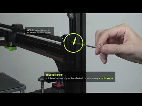
Note - How to adjust tension:
- Whenever frequency values are higher than desired, turn the tensioner block screw anti-clockwise (as a rule of thumb, a quarter turn corresponds to roughly a 10 Hz adjustment).
- If the values are below the desired level, turn the screw clockwise.
- Remember to loosen the set screw on the side of the block.
- Important Note: Your Left and Right Belt needs to have the same frequency values.
- If you are getting frequency readings around ~30 Hz or ~130 Hz, you need to repeat the plucks, those frequencies correspond to an incorrect harmonic. Make sure you obtain at least three consistent frequency readings.
-
Tension the Hybrid belts, aiming for 84 Hz (+-1Hz).
-
Tension the CoreXY belts, aiming for 87 Hz (+- 1Hz).
-
Because adjusting the CoreXY tension can affect the Hybrid tension, we need to check the Hybrid tension again. Repeat steps 10 and 11 until all the belts are plucking with the correct frequency.
-
Now that you've tensioned the belts and reached the desired frequency, we'll proceed with the fine adjustment.
- Move the toolhead(s) to the center of the machine (they must be clear of the motor cages and any PTFE tube guides).
- Gently slide the gantry fully to the back until the joiners contact the stepper motor cages.

- Press both joiners against the stepper motor cages. You will probably feel that one side is making firm contact, and the other has some play. We need to adjust the balance of corexy belt tension until both sides are making firm contact at the same time with no play.
If both sides are making firm contact, no further adjustment is required.
Otherwise, identify the side that does not make firm contact.
- Loosen only the lower set screws on both the left and right tensioner blocks.
Note - Explanation Block:
We will need to slightly decrease the tension on the identified side by turning the tension screw anti-clockwise, and slightly increase the tension on the other side by turning the screw clockwise.
To avoid causing excessive gantry twist, make any adjustments symmetrically on both sides but in opposite directions.
For example, if you tighten the right tensioner, slightly loosen the left tensioner. Do not attempt to straighten the gantry using only one side.
-
Make small adjustments until both joiners make firm contact with the stepper motor cages at the same time.
-
Tighten the gantry screws that were slightly loosened in step 5.
¶ 02. Belt tension - Advanced users only
If you don't feel comfortable analyzing the belt tension graphs, you can move on to the next topic, 04. Input Shaper, where you'll perform part of the diagnostic process that can be done using the belt tension graph.
Belt tension graphs are meant to help diagnose your machine assembly rather than serve as a tuning tool. It's easy to over-focus on them, but they should be seen as a guide for spotting issues rather than a perfect benchmark. Belt tension analysis is a nuanced and evolving subject; for deeper exploration, check out the excellent work by the Klippain Shaketune team.
Warning! Ensure your machine build is complete, wiring is clean, no parts are loose, and the printer is placed on a sturdy surface with nothing resting on or against it. Do not touch the machine during vibration analysis.
This procedure focuses on relative belt tension—verifying that both belts are equally tensioned, which is crucial for smooth motion. Ideally, the belt graph for a V-Core 4 will show smooth lines with two peaks, as illustrated below.

To perform a belt tension graph, just click on the designated button inside the "SCRIPTS" window.

You must now analyse your graph and identify potential issues. This is a very complex and involved process, but here are a few generic most found issues:
-
The two peaks (blue and orange) must be aligned on the same frequency, if they are not vertically aligned, then you need to tension or loosen the belts, and your gantry is most likely twisted. Refer to this guide to help you troubleshoot.
-
Toolhead vibrations typically appear in the 100–150 Hz range and can result from loose screws, damaged printed parts, unsecured wires, or insufficient cable management (e.g., missing zip ties).

-
There is an issue with the belt path: If your graph lacks one or two peaks. It likely means a belt is rubbing against something along its path, such as an idler, motor pulley, or the frame.
- 3.1. In the example below, only one belt path is affected.

- 3.2. In the example below, both belt paths are affected.

-
Lastly, it's important to distinguish between vibrations and swinging.
- 4.1. Vibrations appear as zig-zag patterns on the graph and are usually caused by loose screws on the toolhead or gantry. Loose idler stacks or missing shims can produce the same effect. Carefully inspect the assembly to identify and correct the source.

- 4.2. Swinging appears as smooth curves on the graph and is often caused by the printer resting on an unstable table or uneven floor. Ensure your machine is on a solid, level surface to prevent it from shaking.

¶ 03. Input Shaper
This calibration follows the Klipper documentation steps but they are simplified for the V-Core 4.0.
- Open the SCRIPTS window and click GENERATE SHAPER GRAPHS.

- After completion, open the machine tab (1) and navigate to the input_shaper folder.

Note! You will find four files. Each file name indicates the toolhead (T0 or T1), the axis (X or Y), and the timestamp. Example:
T0_resonances_y_2025-02-17-163419represents a T0 Y-axis input shaper graph created at 16:34:19 on February 17, 2025. Graph Information below.

- Open the Dashboard tab and enable IDEX COPY mode in the IDEX window.
- Click GENERATE SHAPER GRAPHS again.

- Enable IDEX MIRROR mode in the IDEX window.

- Click GENERATE SHAPER GRAPHS again.
-
Open the input_shaper folder. You should now see twelve graphs.
Standard: T0X, T0Y, T1X, T1Y
Copy mode: T0X_COPY, T0Y_COPY, T1X_COPY, T1Y_COPY
Mirror mode: T0X_MIRROR, T0Y_MIRROR, T1X_MIRROR, T1Y_MIRROR -
Open every graph and note down the MZV resonance frequencies and the graph they are from.
-
Open the machine (1) tab and then open the printer.cfg (2) file.

- Copy the code below and paste it inside your printer.cfg. Replace the graph names with the corresponding MZV resonance frequencies you previously recorded in step 8.
[gcode_macro RatOS]
variable_shaper_x_freq: [T0_X, T1_X, COPY_X_AVERAGE, MIRROR_X_AVERAGE]
variable_shaper_y_freq: [T0_Y, T1_Y, COPY_Y_AVERAGE, MIRROR_Y_AVERAGE]
variable_shaper_x_type: ["mzv", "mzv", "mzv", "mzv"]
variable_shaper_y_type: ["mzv", "mzv", "mzv", "mzv"]
Note! To calculate the average value for Copy mode, add the resonance frequencies of T0 and T1 in Copy mode and use the resulting average as the COPY_X_AVERAGE and COPY_Y_AVERAGE.
For Mirror mode, perform the same calculation using the T0 and T1 Mirror mode graphs to obtain the MIRROR_X_AVERAGE and MIRROR_Y_AVERAGE values.
- Click "SAVE & RESTART" at the top right of the printer.cfg page.
¶ 04. Resonance analysis
The real-time analysis tool enables real-time resonance analysis of your printer. This functionality allows you to set the printer to resonate at a specific frequency and direction, facilitating a detailed mechanical assessment. With this tool, you can more effectively diagnose potential mechanical issues within the machine. Find more detailed information about this tool here.
Note: Discover how this diagnostic tool works and how you can apply it.
-

-
If the incorrect toolhead moved, it means the X stepper and DC stepper connectors on the Octopus board are swapped. Disconnect the machine from power and swap the connectors. Check the wiring diagram here.
-
1. Click on the Real-Time Analysis button (1) in the left menu.
-
2. Select the Accelerometer (2).
-
3. Click Start (3) to activate the accelerometer readings.
-

-
4. Select the resonance direction (4):
-
4.1. Use 'Oscillate X' to debug an X-axis Input Shaper spike or noise.
-
4.2. Use 'Oscillate Y' to debug Y-axis Input Shaper spikes or noise.
-
4.3. Use 'Oscillate X-Y' to diagnose resonance in the lower belt line within the belt graph.
-
4.4. Use 'Oscillate X+Y' to analyse resonance in the top belt line within the belt graph.
-
5. Choose the Oscillation Frequency (5) at which you want the machine to resonate.
¶ 05. Beacon set-up
RatOS provides fully automated Beacon Contact model calibration and temperature offset adjustment. Learn more here.
Warning! The extruder and hotend must be free of filament. Make sure to unload it first, otherwise the machine will not be able to perform this calibration accurately.
-
Install the flex plate.
-
This test will show you the quality of your Beacon probing. Run the following command in your console:
BEACON_POKE_TEST
Check the console output - it should look similar to this:
![]()
- Compare your latency values with the following list.
| Score | Notes |
|---|---|
| 0-1 | Extremely low noise, rarely achieved |
| 2-4 | Excellent performance for a typical printer |
| 5-8 | Acceptable performance, machine may have considerable cyclic axis noise |
| 9-11 | Not ideal, may want to verify proper mounting or use thinner stackups |
| 12-14 | Reason for concern, present setup may be risky to continue with |
- RatOS comes with built-in temperature expansion calibration and compensation. To calculate this value run the following command:
BEACON_CALIBRATE_NOZZLE_TEMP_OFFSET
The process will take some time to complete. Check the console output - it should look similar to this:
![]()
The result is automatically saved to the configuration file - no user action is required.
¶ 06. Compensation Mesh
The Beacon Scan Compensation feature in RatOS allows you to compensate for these effects by creating a compensation mesh that corrects proximity measurements based on the actual measured distance between the nozzle and the bed surface at multiple locations across the bed.
- To enable scan compensation, add the following to your printer.cfg:
[gcode_macro RatOS]
variable_beacon_scan_compensation_enable: True
variable_beacon_scan_compensation_profile: "auto"
- To create a compensation mesh run:
BEACON_CREATE_SCAN_COMPENSATION_MESH BED_TEMP=85
Note! Use your target temperatures for the "BED_TEMP=".
Example: PLA — BEACON_CREATE_SCAN_COMPENSATION_MESH BED_TEMP=60
The compensation mesh creation process automatically determines the appropriate mesh name based on the bed temperature. Alternatively, you can specify a custom profile name using the PROFILE parameter, for example:BEACON_CREATE_SCAN_COMPENSATION_MESH BED_TEMP=85 PROFILE="PEI_PC_85"
You'll need a compensation mesh for each build plate and for different bed temperature ranges.
Warning! Make sure the nozzle is clean and that no filament is leaking out of it.
- Print a 150x30mm single layer rectangle in the middle of the build plate.

-
While printing, if necessary, fine-tune using baby stepping.
-
Click the SAVE button in the Mainsail Z-OFFSET section to save the adjustment, or run the Z_OFFSET_APPLY_PROBE command.
¶ 07. Initial VAOC Calibration
Warning! Before we start, never, under any circumstances, use the machine or the console while the VAOC window is open, this will make RatOS throw an error to prevent machine damage.
Learn more about the endstop calibration
-
Endstop calibration is essential to ensure the nozzles are aligned as best as the hardware allows, to reduce the necessary software compensation. Poorly adjusted endstop positions can lead to errors when operating the IDEX printer.
-
It is important to keep in mind that the IDEX machine's coordinates are highly sensitive. This sensitivity is not due to endstop placement or assembly alignment issues. Unlike single-head machines, which rely solely on endstop positions for location accuracy without concern for alignment between the endstop and nozzle, the IDEX machine bases its positioning on the nozzle itself. This is achieved via VAOC, which introduces a degree of potential misalignment if hotends are not assembled with precision. In the IDEX system, slight assembly variations accumulate, leading to a slight misalignment of the nozzles; a few factors may have impact on it:
-
1) Frame Squareness – Any deviations in the frame's structure can affect overall alignment.
-
2) Gantry X Extrusion Length and Joiner Assembly – Small differences in these components directly impact the positioning of the toolheads.
-
3) Toolhead Assembly – Variances in toolhead assembly can add up and affect alignment.
-
4) Z Extrusion Twist – Any twist in the Z extrusion further contributes to positional errors.
-
5) Uneven belt tension.
-
The bed margin also needs to be adjusted accordingly to the new endstop positions.
-
Parking and Load position calibration
-
The parking position ensures the unused toolhead doesn't ooze filament and holds its pressure correctly, staying ready to print at any time. A poorly calibrated parking position will lead to errors in klipper or poor-quality prints. These should be adjusted accordingly to the new endstop positions. Check here for instructions on how to adjust the oozeguard position, if needed.
-

- Press Home All (1) and then click on Z-Tilt (2).

- Run the following command in your console:
_VAOC_RESET

- Disable the steppers by running the following code in your console:
M84
- Navigate to the VAOC tab, and hit start calibration.

ERROR when using VAOC - MOVE OUT OF RANGE
-
Error when trying to use VAOC - Toolhead can't reach the camera in Y
-
We are sorry that you are here! Follow these steps to get the machine working.
-
How to solve: Increase the Y movement range
-
Run the following command:
INCREASE_Y_MAX
-

-
Then run:
RESTART
- If you still get this error after, do it again. This calibration must be done at small increments.
HELP! VAOC Camera freezing.
-
If your VAOC camera frequently freezes, consider the following potential causes:
-
USB Connection: Check where the camera's USB cable is connected. Some users have reported intermittent freezing when the camera is plugged into the Waveshare USB hub. To resolve this, try connecting the camera directly to the Raspberry Pi.
-
Raspberry Pi Model: The processing power of your Raspberry Pi significantly affects the performance of the VAOC interface. Models with more memory, such as the Raspberry Pi 4B (2GB RAM), will provide a smoother experience compared to the 1GB version or the Raspberry Pi 3B.
Note!
-
T0 is automatically selected as the main toolhead, we advise flipping the camera movement right away, this makes adjustment easier, but it's a personal preference. Measure the external diameter of your nozzle with a set of calipers, the standard Phaetus nozzle is 1 mm, insert the value in the settings window. Adjust the pixel rate so the nozzle hole matches the crosshair size.
-

- Adjust the Z position on the right side to achieve a clear focus on the nozzle. Then, drag the nozzle hole to the center of the crosshair.

HELP! Can't focus both nozzles.
-
This indicates that the nozzles are at different heights. Begin by adjusting the focus for T0, then switch to T1 and determine whether the Z focus distance needs to be increased or decreased.
-
1) If the Z focus distance needs to be lowered, the T1 nozzle should be tightened, or alternatively, the T0 nozzle should be loosened.
-
2) If the Z focus distance needs to be increased, the T1 nozzle should be loosened, or alternatively, the T0 nozzle should be tightened.
-
Adjust the Z position on the right side to achieve a clear focus on the nozzle. Then, drag the nozzle hole to the center of the crosshair.
-
Switch between T0 and T1 two to three times to achieve perfect nozzle alignment. Align between each verification if necessary.
Note! A slight drift between nozzles is normal during the first few attempts. Repeat the switching process until both nozzles remain aligned.
-
Once you are satisfied with the nozzle alignment, click the square icon at the top left corner to save and exit to end the VAOC procedure.
-
Run the following command in the console:
CONFIGURE_DC_ENDSTOP
The values are generated automatically into ratos_generated/dc-endstop.cfg:

- Run the following command in the console:
RESTART
- If you need to redo the VAOC calibration, you must first reset using:
_VAOC_RESET
- Run the following command in the console:
RESTART
- Perform a new VAOC nozzle alignment procedure by repeating steps 4 through 9.
Important Note! Validate the calibration:
Open the ratos-variables.cfg file inside the machine tab and check the idex_xoffset value, if the value is higher than 1.0mm or lower than -1.0mm then the printer suffers from mechanical issues like a skewed gantry and/or uneven belt tensioning or belt length.

¶ Z endstop check and calibration
Both nozzles should be at the same height. This is impossible to achieve in real life, due to machining tolerances and assembly variances. Getting them as close together as possible is mandatory to ensure the best IDEX experience and allow for the usage of copy and mirror mode.
- Press Home All (1) and then click on Z-Tilt (2).
- Navigate to the VAOC tab, and hit start calibration.
- Calibrate the XY offsets for T0 by dragging the nozzle into the center of the crosshair.
-
Switch to T1 and calibrate the XY offsets by dragging the nozzle into the center of the crosshair.
-
Switch between T0 and T1 two to three times to achieve perfect nozzle alignment. Align between each verification if necessary.
-
Then click Calibrate Z-Offset.

- Click the square icon at the top left corner to end the VAOC.
- Open the machine console and observe the Z_offset value between T0 and T1. This value should be smaller than 0.07 mm.

🛈 Improve your Z offset
-
PRO TIP: If your value is larger than this, you need to check if both toolheads are correctly assembled, and everything is tightened down. Please go back to step 1 and redo the testing, check if the values from different tests are consistent.
-
If the values are not consistent, it would mean there is a mechanical problem, like a loose nozzle, loose heatbreak screws, loose lead screw coupler, poorly assembled VAOC module and Z endstop, loose toolhead or hotend, etc…
-
If the values are consistent, then you need to figure out which nozzle is the highest. If the Z_offset value is positive, it means that T0 is lower than T1. If the Z_offset value is negative it means that T1 is lower than T0.
-
The easiest fix is trying to loosen and retighten both nozzles.
-
If this doesn't work, you can try to lower the highest nozzle, by using a small shim in between the hotend and the toolhead plate. The small plate that holds the electrical crimps together is generally 0.2mm thick, if you have any available from your kit or toolboard kit, you may use it for this purpose, make sure to measure it before with a good set of calipers (this comes at a cost of lost mechanical strength, this method is only as a last resort).
-
The goal is to achieve a Z_offset lower than 0.05mm, it's impossible to achieve a perfect Z_offset so don't overdo it.
HELP! The Z endstop readings are unreliable.
- Unreliable Z endstop measurements can result from several factors. Below are some potential causes and areas to inspect:
-
Toolhead-Related Issues: If only one toolhead exhibits inconsistent readings, the following issues may be responsible:
-
1) A loose nozzle.
-
2) Accumulation of molten filament in the nozzle.
-
3) The Rapido hotend not being securely fastened to the mounting plate.
-
4) Loose screws on the MGN12C carriage.
-
Z Endstop Assembly Issues:
-
1) The POM insert may be damaged or excessively tight within the VAOC body, causing binding of the Chicago bolt.
-
2) The Chicago bolt itself may not be properly tightened.
-
Carefully inspect the Z endstop assembly to ensure all components are correctly installed and functioning as intended.
¶ 07. Skew Calibration
Skew correction is meant to compensate for a 3D printer assembly which is not perfectly square, the software makes small changes to the toolhead movement, maintaining a perfectly square trajectory. Every detail during the frame assembly may cause a slightly twisted frame, even the screws tightness. Making sure the machine is as square as one can get by hand is very important before advancing to software skew calibration.
The V-Core 4 has a 3-point kinematic bed levelling system that helps to mask XZ and YZ skew problems. If the build was successful and all Z rails are properly aligned, the Z squareness shouldn't be a problem, otherwise, a skew calibration should be done for all planes. In this guide we'll only focus on the XY plane, the procedure is the same for the other axis, more information here.
- Start by downloading the Skew_correction_tool.stl. Then open it inside your slicer. If this is your first time following this guide, please follow the Slicer installation first, then get back to this step.
Caution. When slicing the model, make sure the A corner is pointing to the origin of the print area.

- Guarantee that no skew correction is running on your machine, check that variable_skew_profile is commented out in the macro configuration section. or type the command below in the terminal. For more information, click here.
SET_SKEW CLEAR=1
The [skew_correction] module requires 3 measurements; the length from Corner A to Corner C, the length from Corner B to Corner D, and the length from Corner A to Corner D.

Let's take the following measurements as an example:
AC= 141.15mm
BD= 140.9mm
AD= 99.65mm
- Go into the printer.cfg and add the following lines:
[gcode_macro RatOS]
variable_skew_profile: "my_skew"
- Click "SAVE AND RESTART" at the top right of the printer.cfg window, then run the following command in your console:
NOTE: Replace the "AC, BD, AD" text with your values.
SET_SKEW XY=AC,BD,AD
Note! With the previous example, we have:
SET_SKEW XY=141.15,140.9,99.65
- Run the following command in your console:
SKEW_PROFILE SAVE="my_skew"
- Run the following command in your console:
SAVE_CONFIG
- Re-print the test, make sure AC=BD. If not, double check all measurements and start this calibration again.
¶ Next Guide
- Continue to the next guide: 04. Operation & Slicer