¶ Before Getting started...
It’s important to get familiarized with some terms:
- T0 - Left toolhead
- T1 - Right toolhead
- X-axis - Left to right direction
- Y-axis - Front to back direction
- stepper_X - Left toolhead X stepper [L]
- stepper_Y - Right stepper [R]
- dual_carriage - Right toolhead X stepper (DC stepper)
- VAOC - Visually Assisted Offset Calibration
- Z endstop - The Chicago bolt on the VAOC, where the nozzles probe
Note!
At this point the hybrid Top Y belts should have been installed - Follow these steps to install them.
¶ 01. X-axis direction
- Run the following command in your console to disable all of the stepper motors:
M18
-
Manually move both toolheads to the center of the build plate, ensuring at least 100 mm of space between them.
-
Run the following command in your console, to tell Klipper the toolheads are roughly centered.
SET_CENTER_KINEMATIC_POSITION
HELP! The center kinematic position.
-
The set center kinematic position command is used to directly define the central position of an object or component within the workspace.
-
Key characteristics:
- Allows the object to be repositioned immediately and in a controlled manner;
- Applies only to position, without considering physical or motion constraints;
- Recommended for configuration tasks, calibration, or setting the initial position of the equipment. -
Recommendation: use this command with caution, as direct repositioning may lead to unexpected results if other elements are present or interacting in the environment.
- Use the Mainsail buttons to move the toolhead 10mm to the left and right, ensuring it is moving in the right direction.

- If the T0 X-axis is moving in the expected direction, skip to step 7.
- 5.1. If the toolhead moved, but in the wrong direction, navigate to the 'Machine' section in the left-hand menu and open the printer.cfg file. Locate the [stepper_x] section and invert the direction pin by adding, or removing, the ! in front of the Dir" pin label, as shown below.

HELP! The toolhead moved in the wrong direction.
- If the incorrect toolhead moved, it means the X stepper and DC stepper connectors on the Octopus board are swapped. Disconnect the machine from power and swap the connectors. Check the wiring diagram here.

-
Click "SAVE & RESTART" at the top right of the **print.cfg page.
-
Run the following command in your console, to activate T1:
SET_DUAL_CARRIAGE CARRIAGE=1
- Select T1 by clicking on the "T1" button in the "EXTRUDER" window (see image above), then use the mainsail buttons to move T1 10mm to the left and right, ensuring it is moving in the right direction.
- If the T1 X-axis is moving in the expected direction, this chapter is complete!
- 9.1. If the toolhead moved, but in the wrong direction, navigate to the 'Machine' section in the left-hand menu and open the printer.cfg file. Locate the [dual_carriage] section and invert the direction pin by adding, or removing, the ! in front of the Dir" pin label, as shown below.

¶ 02. Y-axis direction
- Run the following command in your console to disable all of the stepper motors:
M18
-
Manually move both toolheads to the center of the build plate, ensuring at least 100 mm of space between them.
-
Run the following command in your console:
SET_CENTER_KINEMATIC_POSITION
HELP! The center kinematic position.
- The set center kinematic position command is used to directly define the central position of an object or component within the workspace.
- Key characteristics:
- Allows the object to be repositioned immediately and in a controlled manner;
- Applies only to position, without considering physical or motion constraints;
- Recommended for configuration tasks, calibration, or setting the initial position of the equipment. - Recommendation: use this command with caution, as direct repositioning may lead to unexpected results if other elements are present or interacting in the environment.
- Select the 1mm square (marked in orange) and move the Y axis in a very small amount, 3mm maximum.

Warning! If any of the Y steppers are inverted, the machine can get damaged with excessive move distances.
- If the Y-axis is moving in the expected direction, restart klipper and you are done, please proceed to the next sanity check.
- If the gantry moved but in the wrong direction. Navigate to the printer.cfg file and locate the [stepper_Y] and [stepper_Y1] sections. You need to invert the direction pin on both steppers, by adding or removing
!in front of the"dir"pin label, as shown below.
- If the gantry moved but in the wrong direction. Navigate to the printer.cfg file and locate the [stepper_Y] and [stepper_Y1] sections. You need to invert the direction pin on both steppers, by adding or removing

HELP! The gantry is twisting when moving the Y-axis.
-
If the gantry twists when moving the Y-axis, it indicates that one of the Y stepper motors is inverted. You will need to determine whether the Y stepper or the Y1 stepper is inverted and take appropriate action. This can be resolved by inverting the direction pin of only one Y stepper, as explained above.
-

- Click "SAVE & RESTART" at the top right of the printer.cfg page.
- Repeat steps 1 to 4 to ensure the toolhead is moving in the right Y direction.
¶ 03. Z-Axis Stepper motor directions
- Run the following command in your console to disable all of the stepper motors:
M18
-
Lower the Z arms by 30mm by hand, rotating the lead screws counter-clockwise slowly.
-
Verification of the Z stepper motors
Warning! Only the stepper motor you are verifying should move, as shown in the image below. If any other stepper motor moves, please note which one it is. Once all three stepper motors have been tested, we will correct any which are connected incorrectly.

- 3.1. Run the following command in your console and take note of which Z stepper moved. Only Stepper Z should move.
STEPPER_BUZZ STEPPER=stepper_z
- 3.2. Run the following command in your console and take note of which Z stepper moved. Only Stepper Z1 should move.
STEPPER_BUZZ STEPPER=stepper_z1
- 3.3. Run the following command in your console and take note of which Z stepper moved. Only Stepper Z2 should move.
STEPPER_BUZZ STEPPER=stepper_z2
- If all three Z-axis stepper motors move correctly, please continue following this guide as your Z-axis is ready for action.
HELP! If not, refer to the notes you took earlier and swap the connectors on the Octopus board accordingly. Click here to view the Z stepper wiring diagram.
- Run the following command in your console:
SET_CENTER_KINEMATIC_POSITION
- Use the Mainsail buttons to move the z arms 10mm up and down. Carefully observe the movement of each Z arm.

HELP! Z steppers are moving in the wrong direction.
- If any of them is moving in the wrong direction, you will need to remove the "!" before the direction pin in the printer.cfg file, as the picture below shows:

¶ 04. Endstops
- Run the following command in your console to disable all of the stepper motors:
M18
-
On the left-side menu, click "Machine" (1), and find the endstops box (2).

-
Hit the refresh button on the right and check if all endstops show as "OPEN".

- Move the gantry and the toolhead to the positions indicated in the image.

Warning!
Make sure that, at the end of the movement, all endstops are triggered.
- Move the gantry carefully to avoid damaging the endstops.
- Do not use excessive force, the movement should be smooth and controlled.
-
Hit the refresh button and they should show "TRIGGERED".

-
Run the following command in your console, to check if the Z endstop on VAOC is working properly:
Z_OFFSET_QUERY_PROBE

HELP! Endstop isn't working properly.
- If one or more endstops are not functioning correctly, there are several ways to diagnose the issue. The problem generally comes from one of three possibilities: an incorrect port connection, a faulty endstop, or a wiring issue. We recommend the following troubleshooting steps:
- Swap the connector of the non-working endstop with one that is working on the Octopus board. This will help determine if the issue follows the endstop to the new port or remains with the original Octopus port. If the problem stays on the same port, it could indicate that the connector is incorrectly placed on the Octopus board or there is a configuration mismatch. Please verify that the connector matches the port specified in the RatOS configurator and wiring guide.
- Replace only the endstop at the end of the wire. If this resolves the issue, the endstop itself may be damaged.
- Use a multimeter to check the continuity of the wiring. If there is no continuity between the crimps on the connectors, it may indicate a faulty wire that needs to be replaced.
¶ 05. Hotend + fans
- Run the following command in your console to disable all of the stepper motors:
M18
- Slowly and carefully move the gantry to the front of the machine, and the toolheads to the middle of the gantry.
- Remove the silicone sock from the toolhead T0.
- Install the nozzle if it is not already installed. Tighten it with your fingers. Do not use any tools at this stage.
- Carefully reinstall the Silicone Sock onto the hotend T0.
- Turn on the "Fan" at 40% for T0.

HELP! The 4028 isn't functioning properly.
-
Please check the following link for more information on the 4028 fan. You can find the fan control toggle under the "Miscellaneous" window in Mainsail.
-
If the 4028 won't turn on, go back to the RatOS configurator, hardware selection tab and check if every component is correctly configured. This fan should be selected as a PWM 4pin fan as the image below shows:
-

-
If everything is configured correctly, you should check the wiring connections. Ensure that the 12V jumper is set correctly (here). The most likely issue is that the fan is not receiving power, possibly due to problems with the +12V and GND wires. Inspect the crimps on the small Molex connector. You can use a multimeter to check for continuity.
HELP! The 4028 FAN is stuck at 100%.
- If the 4028 fan is stuck at 100%, it may indicate a faulty PWM connection to the toolboard. Inspect the crimps on the PWM wire at the toolboard here.
- In the dashboard, find the calibration window. Perform a PID calibration for the hotend. Type 0 for TOOLHEAD placeholder, then insert the temperature 240 and press "SEND".

Important Notes:
-
When the PID starts the 4010 hotend cooling fan should be spinning.
-
If the hotend cooling fan doesn't turn on, you'll need to check the wiring connections and toolboard connector - more here.
-
Once the calibration is complete, a message will appear in the console.
-
Click "SAVE CONFIG" in the top-right corner of the screen, and the machine will reboot with the new default values.
-
Wait for the hotend to fully cool down before continuing.
-
Remove the sock carefully.
-
Heat the Extruder/Hotend to 280ºC.
-
After the temperature stabilizes, tighten the nozzle properly.
Warning! Be careful as the hotend is very hot and you can easily burn yourself. Over-tightening the nozzle can result in permanent damage. Phaetus recommends 2.5Nm of torque when hot-tightening the Rapido 2 nozzle.
- Set the extruder temperature to 0ºC and allow it to cool down completely. Once it has cooled, install the silicone sock carefully over the nozzle.
¶ 06. Home Sequence
Before starting, ensure the machine has successfully passed all sanity checks.
As a precaution, keep your finger above the Emergency Stop button to react quickly to any unexpected behaviour.

- Run the following command:
BEACON_INITIAL_CALIBRATION
Process notes:
- 1. The machine will home all axes and run a fully automated calibration process.
- 2. If a tolerance error occurs, simply repeat the command until it completes successfully.
- 3. During calibration, the LED indicator will turn on once the contact system detects a strong enough signal. This typically happens 5–10 mm before reaching the metal target, providing enough time to trigger an emergency stop if needed.
¶ 07. Build Plate Preparation
Note:
The bed heater and surface magnetic pad should not have been installed before this chapter.
- Run the following command in your console:
M18
Warning:
It is normal for the bed to be tilted after assembly.
-
Manually adjust each lead screw by rotating it to achieve a roughly leveled bed.
Precision is not required at this stage, as the machine will refine the leveling process later. -
Move the toolhead to each designated Z position and make the necessary adjustments to ensure the nozzle is approximately 5 mm from the bed.

Note:
You may use the Beacon's red light as a reference, adjusting until the light activates.
-
Now home the machine and perform a Z-Tilt calibration. This can be found on the dashboard page.

-
Click the home icon inside the HeightMap tab.
Once the printer has homed, click Calibrate and provide a name for the mesh. RatOS will create an initial bed mesh.


-
Inspect your mesh.
Enable Scale Gradient and move the Scale Z-max slider fully to the right.
If the mesh looks flat like the image below, proceed to 08. Bed Wiring.

-
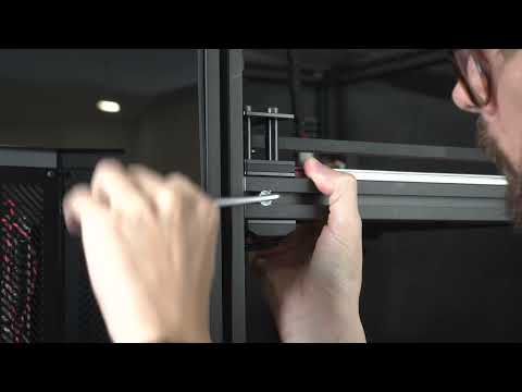
If your bed mesh is not flat and appears tilted or twisted (like the image below), verify the alignment and squareness of your frame.

Frame Alignment and Squareness Adjustment
- The image below shows a twisted bed mesh. This indicates a non-square frame. You will observe a peak or depression at point C or D.

- Identify the peak in height, indicated by the blue arrow in the bed mesh.
- Adjust point C by loosening the highlighted quick connectors.
(Only C' and D' can be adjusted. Do not adjust A or B.) - Gently tap the bottom extrusion to lower the peak.
- Re-tighten the quick connectors and perform a Z-Tilt calibration.
- Run another bed mesh scan. If the peak remains, repeat the process. If there is a depression instead, push the extrusion downward.
- Make small adjustments in each iteration until the mesh is flat.

-
Shut down your machine and unplug it from the mains electricity supply.
-
Before applying the heater pad, open the electronics enclosure and disconnect the bed thermistor from the Octopus.
Do not apply the heater pad while it is still connected.
10.Apply the heater pad carefully.
It cannot be removed or repositioned once placed.
11.Peel back about one inch of the protective sheet from one side.
12.Align the heater pad centrally on the bottom of the aluminum bed and press down to secure the edge.
13.Gradually peel the protective sheet while adhering the heater pad.
Use a flat plastic tool (e.g., an old credit card) to remove air bubbles.


14.Using the same method, apply the magnetic surface to the top of the bed and install it on the V-Core 4.
15.Wash or wipe the flexplate with warm water and soap before first use, then dry it with a microfiber cloth to remove manufacturing residue.
Build Plate Cleaning and Maintenance:
A dirty build plate will lead to adhesion issues that might be confused with first-layer squish/ Z offset calibration problems. The included textured PEI Flexplate doesn't require any type of adhesive; it’s a ready-to-print surface on its own. Regularly wipe your PEI surface down with 70-91% isopropyl alcohol to ensure any grease, or other residues, that may have accumulated on it are removed. This will help increase your surface adhesion greatly.
¶ 08. Bed Wiring
-
After placing the bed assembly on the Z arms again, wire the bed wires as the following image shows:
1.1. Insert the bed wires through the collar on the electronics panel. Secure the cables in the appropriate place, routing the zip ties as shown in the figure below.

1.2. Route the bed thermistor cable as shown.

-
Complete the wiring connections for the bed heater, follow here.
-
Reinstall the electronics enclosure lid, making sure to reconnect the 120 mm fan according to the steps previously performed.

¶ 09. Bed PID
Note!
PID stands for proportional integral derivative and it aims at making the heating process more efficient and consistent. Efficiency is important during heating to consume less energy, consistency is key for print quality.
-
To perform a bed PID calibration, locate the "Calibration" window.
-
Click on the "PID CALIBRATE BED" button (orange square).
-
Select an average temperature at which you expect to print most often.
A good starting point is:- 60ºC for PLA
- 80ºC for PETG
- 110ºC for ABS/ASA
Click "SEND" and wait for the calibration to complete.

- Once the calibration is finished, go to the console and type:
SAVE_CONFIG
- Klipper will restart itself with the new PID values saved to the configuration.
¶ 10. Switch to Performance Mode
After confirming the machine is working properly, switch to performance mode for increased speed and accuracy, ensuring the electronics enclosure fan is operating correctly.
- On the left-side menu, click "Configurator" (1), then "Setup Wizard" (2).

- Select the Hardware tab.

- Scroll down and activate the "Performance mode".

- Scroll further down and click "Next". Then, click "Confirm And Save".

¶ Next Guide
- Continue to the next guide: 03. Calibration